CNC Machining for Custom Carbon Fiber Parts
When it comes to manufacturing precision custom carbon fiber parts, CNC machining stands out as the go-to method for engineers and product designers across industries. Unlike molding or layup processes that require expensive tooling, CNC machining for carbon fiber delivers complex geometries directly from CAD files with remarkable accuracy. Whether you’re developing a lightweight drone frame, a high-performance automotive bracket, or a robotic arm component, understanding how CNC machining carbon fiber parts work can dramatically improve your product development cycle.
Why CNC Machining for Carbon Fiber?
The appeal of CNC machining carbon fiber composite materials goes beyond simple convenience. Carbon fiber reinforced polymers present unique challenges that traditional machining methods struggle to handle consistently. The abrasive nature of carbon fibers quickly dulls conventional cutting tools, while improper techniques can cause delamination, fiber pullout, and surface damage that compromises part integrity.
CNC machining addresses these challenges through controlled cutting parameters, specialized tooling, and precise numerical control. A well-configured CNC machine can achieve tolerances down to ±0.05mm, producing parts that fit assemblies perfectly without secondary fitting operations. This level of precision becomes essential when multiple custom carbon fiber parts must align in complex assemblies.
Another compelling reason to choose CNC machining carbon fiber parts is design flexibility during prototyping. Engineering changes happen frequently in product development, and CNC machining accommodates these shifts without requiring new molds or tooling. You can iterate your design multiple times, test functional prototypes, and refine your geometry—all while keeping development costs predictable.
Batch production consistency also favors CNC machining. Once a program is dialed in, every subsequent part emerges identical to the last. This repeatability matters enormously for applications where mechanical properties must remain consistent across production runs. Aerospace suppliers, medical device manufacturers, and automotive OEMs all depend on this consistency when specifying carbon fiber components.
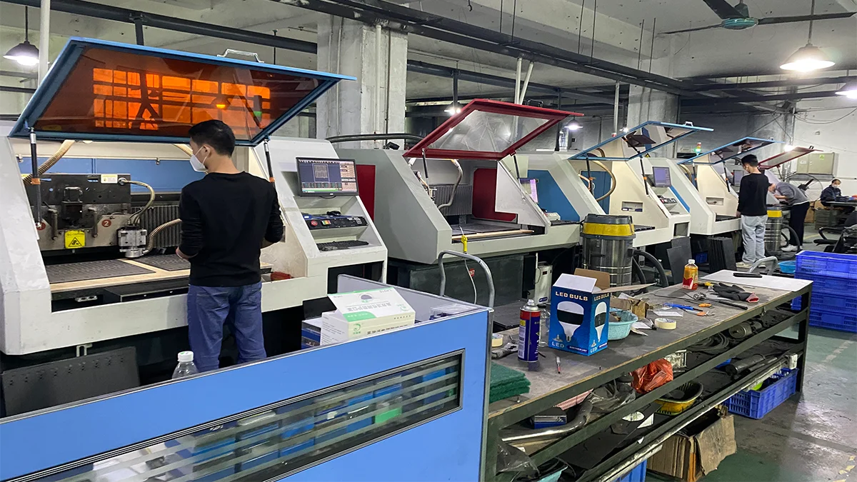
The CNC Machining Process for Carbon Fiber
Understanding the carbon fiber CNC machining workflow helps you plan your project more effectively. The process begins with material preparation—typically selecting appropriate carbon fiber sheet or tube stock that matches your thickness and weave pattern requirements. Prepreg sheets offer superior fiber volume fraction for structural applications, while wet layup sheets provide cost-effective solutions for non-critical components.
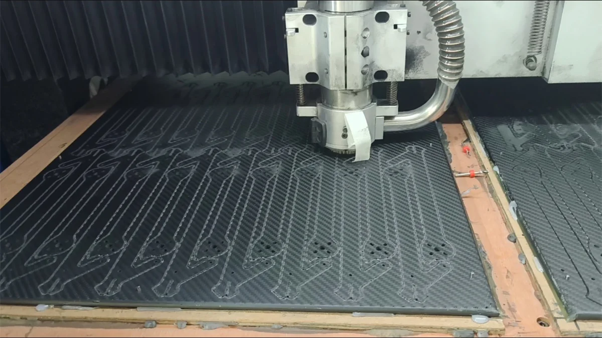
Programming the CNC machine involves converting your 3D model into toolpaths that the machine can execute. This step requires understanding of carbon fiber-specific cutting strategies. Climb milling generally produces cleaner edges than conventional milling when working with carbon fiber composites. The cutting direction matters because fibers tend to pull away from the tool when machined incorrectly, creating fuzzy edges and compromised surfaces.
During cutting operations, the machine performs several essential functions. Profiling creates outer contours and complex shapes. Pocketing removes material from interior areas while leaving walls at specified thicknesses. Drilling produces holes for fasteners and assembly features. Counter-sinking and chamfering prepare edges for hardware installation and improve cosmetic appearance. Each operation uses optimized feed rates and spindle speeds to minimize delamination risk.
Tool selection significantly impacts finished part quality. Solid carbide end mills with diamond-like carbon coatings resist abrasive wear from carbon fibers. Geometry matters too—sharp cutting edges produce cleaner cuts, while appropriate helix angles help evacuate chips before they can cause surface damage. Many shops dedicated to CNC machining carbon fiber parts maintain separate tool sets optimized specifically for composite work.
Chip management deserves particular attention during carbon fiber operations. Unlike metals that produce continuous chips, carbon fiber generates abrasive fragments that can embed in machined surfaces if not properly evacuated. Flood cooling helps control heat and flush chips, though some applications require dry machining to avoid moisture contamination of the composite.
Designing for CNC: What Engineers Need to Know
Successful CNC machining carbon fiber parts start with design decisions that optimize the manufacturing process. While CNC offers tremendous flexibility, following certain design guidelines reduces cost, improves quality, and minimizes the risk of manufacturing defects.
Tolerance specifications should reflect actual assembly requirements rather than pursuing unrealistic precision. Standard tolerancing for CNC machined carbon fiber parts typically runs ±0.1mm for non-critical dimensions and ±0.05mm for critical features. Tighter tolerances increase machining time and inspection costs, so specify precision only where genuinely needed.
Minimum wall thickness recommendations depend on your part geometry and loading conditions, but generally, 1.5mm walls provide reasonable handling strength for most applications. Thinner sections risk damage during machining and assembly while potentially flexing excessively under load. Ribbing and stiffening features can maintain stiffness while reducing overall material usage.
Inside corner radii should be maximized whenever possible to reduce stress concentrations and improve mold flow in related processes. For CNC machining carbon fiber parts, minimum inside radii of 2-3mm work well with standard tooling. Sharp corners create stress risers that can initiate crack propagation under dynamic loading.
Hole placement requires careful consideration of edge distance. Holes too close to part edges risk cracking, while holes near each other can create weak zones between them. A general guideline maintains at least 2x hole diameter between hole centers and a minimum 1.5x diameter from holes to edges. These relationships become especially critical for load-bearing applications.
Common Custom Carbon Fiber Parts
Across industries, engineers specify CNC machining carbon fiber parts for applications demanding high stiffness-to-weight ratios and dimensional stability. The following table summarizes common part categories and their typical requirements:
| Application | Typical Thickness | Key Requirements | Tolerance Class |
|---|---|---|---|
| Drone Frames | 2-6mm | Lightweight, balanced, fatigue resistant | Medium (±0.1mm) |
| UAV Components | 3-10mm | Structural integrity, vibration dampening | High (±0.05mm) |
| Automotive Brackets | 4-12mm | Load capacity, thermal stability | Medium (±0.1mm) |
| Robotic Arms | 5-15mm | Precision, repeatability, stiffness | Very High (±0.02mm) |
| Sports Equipment | 2-8mm | Aesthetic finish, consistent weight | Low-Medium (±0.2mm) |
| Industrial Fixtures | 8-20mm | Dimensional stability, durability | Medium (±0.1mm) |
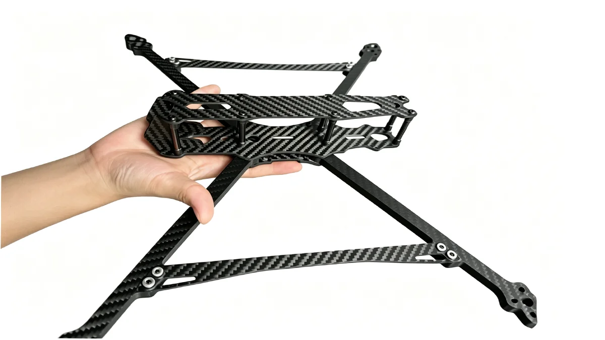
The drone and unmanned aerial vehicle market has become a major driver for CNC machining carbon fiber parts. Racing quadcopters, commercial inspection platforms, and military UAVs all rely on carbon fiber structures that can withstand aggressive maneuvers while keeping weight minimal. These parts often feature complex cutouts for electronics mounting, ventilation, and weight optimization.
Automotive applications increasingly incorporate custom carbon fiber components in performance vehicles and electric cars. Battery enclosures, motor mounts, and structural brackets benefit from carbon fiber’s combination of light weight and high strength. CNC machining delivers the precision needed for these safety-critical parts while accommodating the custom geometries that vehicle integration requires.
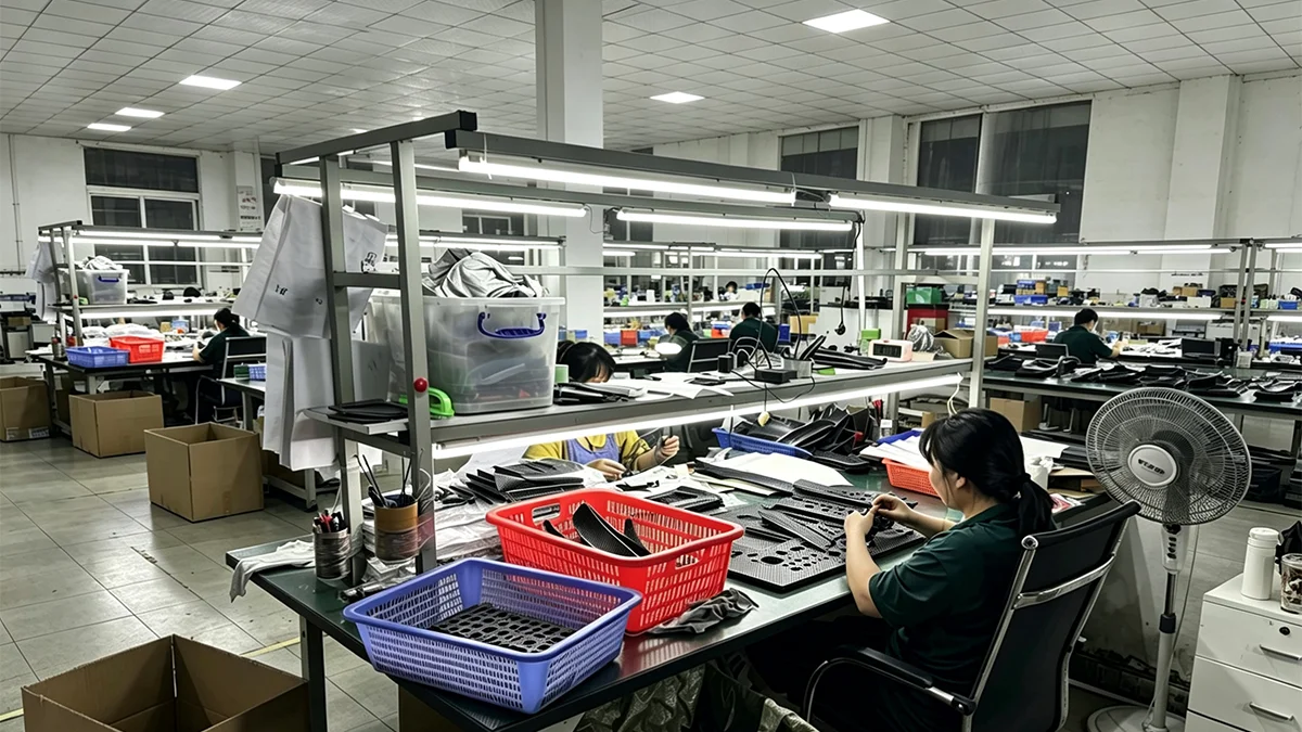
Quality Control and Tolerances
Ensuring that CNC machined carbon fiber parts meet specifications requires systematic quality control throughout the manufacturing process. Dimensional verification forms the foundation of any inspection program, but surface quality and structural integrity deserve equal attention.
First article inspection typically involves measuring every critical dimension on initial parts from a production run. This establishes baseline conformance and identifies any systematic issues before full production begins. Coordinate measuring machines provide high-precision verification for complex geometries, while digital calipers and micrometers handle straightforward linear measurements efficiently.
Surface inspection addresses cosmetic requirements and potential delamination concerns. Visual examination under proper lighting reveals surface defects, edge quality issues, and fiber exposure. For critical applications, ultrasonic testing or thermography can detect internal defects invisible to visual inspection. These advanced methods add cost but provide confidence in structural integrity.
Documentation practices vary based on application criticality. Aerospace and medical applications typically require comprehensive inspection reports with statistical data, while consumer products may accept simple go/no-go inspection. Regardless of formality, maintaining records enables traceability and supports continuous improvement in manufacturing processes.
Cost and Lead Time Considerations
Understanding the economics of CNC machining carbon fiber parts helps you plan budgets and timelines realistically. Several factors influence final costs, and strategic decisions early in design can significantly reduce expenses.
Material costs depend on carbon fiber type, sheet size, and availability. Standard modulus carbon fiber sheets cost less than intermediate or high modulus variants. Common sheet sizes offer better pricing than non-standard dimensions, so designing parts to utilize standard stock reduces material waste and expense.
Machine time constitutes the largest portion of manufacturing cost for most CNC machining carbon fiber parts. Complex geometries requiring extensive cutting, fine tolerances needing slower feeds, and multiple setups all increase time and expense. Simplifying part geometry, loosening tolerances where possible, and designing for efficient nesting all contribute to cost reduction.
Lead times typically range from a few days for standard parts from established suppliers to several weeks for complex custom components requiring specialized tooling or inspection protocols. Expedited service usually carries premium pricing, so realistic scheduling from project inception prevents costly rush charges. Most professional CNC shops provide quotes within 24-48 hours and can deliver production quantities within 2-3 weeks for typical applications.
Volume considerations affect economics significantly. While unit costs decrease with larger quantities due to setup amortization, carbon fiber parts rarely achieve the economies of scale seen in high-volume metal stamping. For very high volumes, alternative processes like compression molding or filament winding may offer better economics despite higher tooling costs.
Get Started with Your Custom Carbon Fiber Project
CNC machining carbon fiber parts offers a powerful combination of design flexibility, precision, and production consistency that serves industries from aerospace to consumer electronics. By understanding the capabilities and considerations outlined here, you can make informed decisions that balance performance requirements with practical manufacturing constraints.
Whether you need a single prototype or a production run of hundreds, working with an experienced carbon fiber machining partner accelerates your development timeline and ensures quality results. Share your CAD files and specifications to receive a detailed quote and manufacturing review.
Ready to bring your carbon fiber design to life? Contact our engineering team for a complimentary quote on your CNC machining project.