Design for CNC Machining: How to Avoid Delamination and Cut Costs on Carbon Fiber Parts
Designing lightweight components from high-strength composites demands a fundamentally different approach than machining standard isotropic metals like aluminum or steel. Because continuous carbon fiber laminates consist of alternating directional carbon tows bonded by a polymer matrix, standard milling cutter dynamics can induce severe edge fraying, fiber breakout, or catastrophic interlaminar delamination. Here is a practical Design for Manufacturability (DFM) guide to help engineers optimize CAD geometries, prevent structural defects, and slash manufacturing costs on carbon fiber CNC machining projects.
1. Understand What Causes Delamination During Milling
Interlaminar delamination occurs when the axial and shear cutting forces generated by a rotating tool exceed the bond strength of the resin matrix. In composite milling, this defect manifests in two critical zones:
- Top-Ply Peeling (Peel-Up): Occurs when upward axial forces from traditional up-cut helical flutes pull the surface fibers away from the core plies before shearing them cleanly.
- Bottom-Ply Push-Out: Occurs during high-speed plunge drilling or down-cutting when tool exit pressure forces the unsupported bottom-most plies outward, separating them from the cured epoxy base.
- Abrasive Tool Wear: Carbon fibers are inherently ceramic-like and abrasive. As cutting edges dull, tool friction spikes exponentially, generating heat that softens the epoxy matrix and triggers micro-cracking along cut perimeters.
2. Five CAD Rules to Reduce Delamination and Lower Cost
Rule 1: Specify Generous Internal Corner Radiuses
Milling tools are cylindrical; cutting a sharp 90° internal pocket requires micro-diameter endmills that vibrate, wear out prematurely, and multiply machine cycle time. Always specify an internal corner radius at least 15% larger than the cutter radius (e.g., use an R1.75mm or R2.0mm corner for a standard 3.0mm diameter router bit). This allows the tool to transition smoothly through corners without pausing and inducing localized heat buildup.
Rule 2: Integrate a 45° Edge Chamfer
Sharp 90° edges on composite brackets and drone chassis are prone to handling damage and chipping. Integrating a subtle 0.5mm to 1.0mm 45° edge chamfer removes vulnerable perimeter fiber tips. This chamfer dramatically increases the impact survivability of components such as 3mm carbon fiber sheet drone arms during drops and high-g collisions.
Rule 3: Keep Fastener Holes at Least 1.5× Hole Diameter from the Edge
Placing screw holes too close to sheet perimeters creates weak resin bridges. To prevent edge blowout during both machining and structural torque loading, keep the minimum distance between the hole edge and the part border at least 1.5 times the hole diameter (or 2.0 times the plate thickness, whichever is greater).
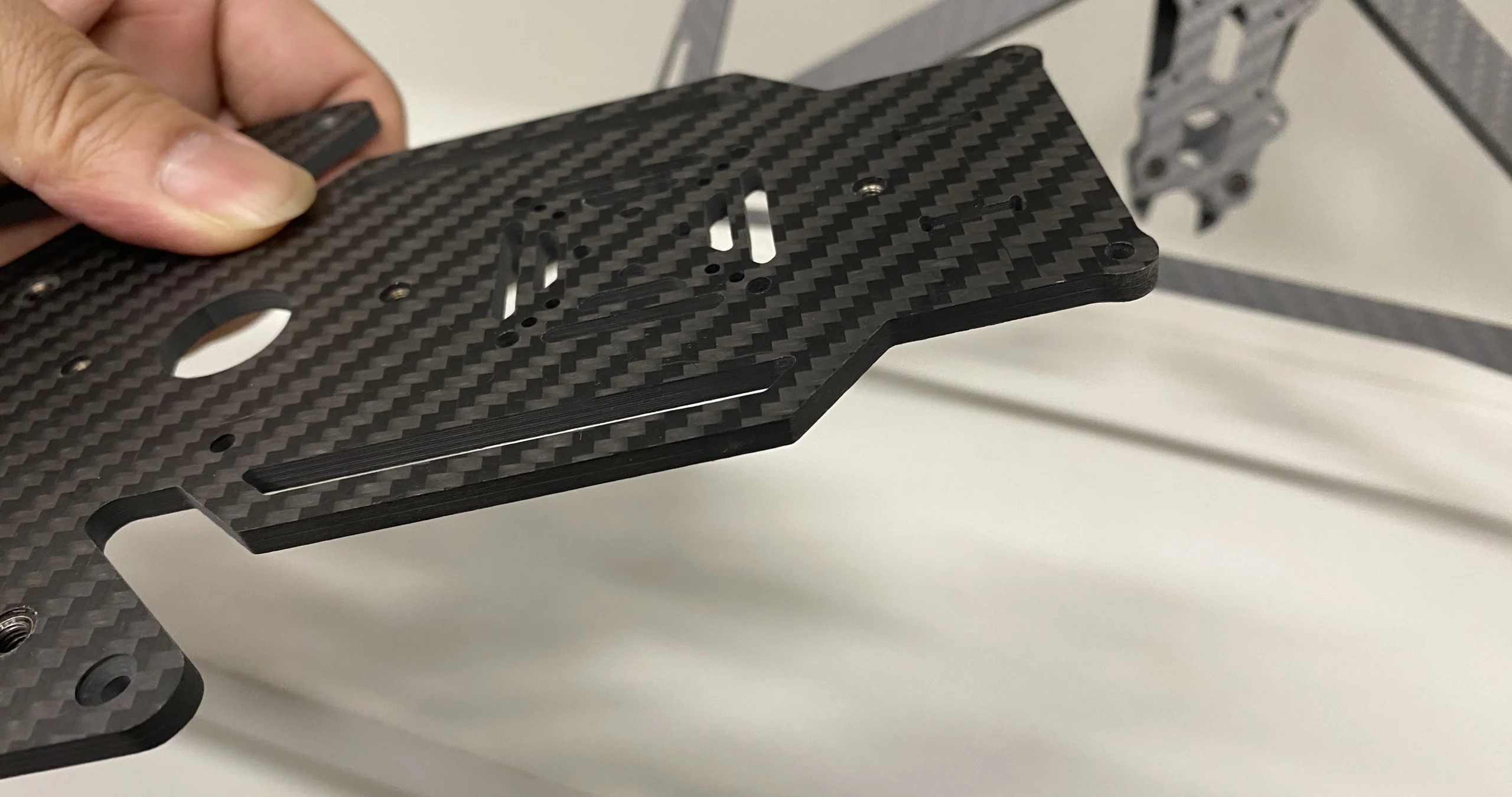
CAD optimization: Generous corner radiuses and edge chamfering prevent fiber chipping and excessive tool wear.
Rule 4: Avoid Through-Threads on Thin Panels (Under 2.5mm)
While solid 3mm plates support direct M3 self-locking (~2.5 turns), tapping through thin 1.0mm–2.0mm composite plates often shears internal fibers under minimal clamping torque. For plates below 2.5mm, design clearance holes for countersunk screws or pocket recesses for press-fit brass/aluminum standoffs instead of direct thread cutting.
Rule 5: Keep Wall Thickness Proportional to Depth
Deep, ultra-thin ribs in carbon fiber composites deflect under cutter pressure, resulting in poor dimensional tolerances and delamination. Keep thin-wall features at least 1.5mm wide, and avoid aspect ratios where wall height exceeds 4 times wall thickness unless supported by custom sacrificial backing jigs.
3. Workshop Tooling: How Professional CNC Machinists Prevent Defects
Even optimal CAD geometry will fail if processed with standard metal-cutting endmills. At our Shenzhen manufacturing facility, we implement aerospace-grade composite routing standards:
| Tool / Process | Why It Matters | Quality Impact |
|---|---|---|
| CVD Diamond-Coated Cutters | Diamond coatings withstand severe abrasive carbon fibers up to 10× longer than standard tungsten carbide. | Maintains sharp cutting shear, zero thermal softening, pinhole-free edges. |
| Compression Router Bits | Features opposing up-cut and down-cut flutes that compress both top and bottom surface plies inward. | Completely eliminates both top peel-up and bottom push-out delamination. |
| High-Speed Air Cooling & Dust Extraction | Suppresses localized friction temperatures without using liquid coolants that can contaminate unsealed edges. | Prevents resin degradation and ensures a clean, spark-free operating environment. |
| Vacuum Fixture Tables | Distributes multi-ton clamping force evenly beneath the composite sheet without mechanical clamp distortions. | Maintains strict ±0.05mm flatness across plates up to 3000mm × 8000mm. |
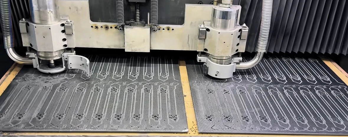
Compression routing geometry directs cutting forces inward, sealing edges against interlaminar separation.
4. Tolerances: What Is Realistic and Cost-Effective?
Tightening tolerances without structural justification is the quickest way to inflate machining costs. Because cured carbon fiber has a low coefficient of thermal expansion (CTE) but slight elastic micro-springback, we advise aligning your CAD callouts with the following realistic standards:
- Outer Profile & Cutout Contours: Standard production tolerance of ±0.10mm is highly economical; precision CNC can achieve ±0.05mm for precision locating pins.
- Hole Diameters: Typically held to ±0.05mm for clean press-fit hardware or clearance bolt patterns.
- Sheet Thickness: Compression-molded plates maintain ±0.08mm to ±0.10mm across the sheet; precision double-sided ground plates achieve ±0.05mm.
Conclusion: Streamlining Your Composite Prototyping
Optimizing carbon fiber parts for CNC machining is straightforward once you respect the directional physics of composite laminates. By adopting generous internal radiuses, chamfering outer edges, selecting compression tooling, and adhering to practical tolerance thresholds, you can produce aerospace-grade components that are splinter-free, structurally resilient, and cost-efficient to manufacture.
Need Precision CNC Machined Carbon Fiber Parts?
Upload your CAD files (.DXF, .DWG, .STEP) directly to our engineering team. We deliver multi-axis spark-free CNC parts with zero delamination and tolerances down to ±0.1mm.