Antenna Mast Selection: Carbon Fiber vs Aluminum vs Fiberglass
Choosing the right antenna mast material is not just about strength and cost — it is about signal integrity. The material surrounding or supporting your antenna directly affects RF performance. Whether you call it an antenna mast, antenna pole, or antenna support, the material choice matters. Here is how to evaluate carbon fiber, aluminum, and fiberglass for your next antenna installation.
Why Material Matters for Antenna Masts
An antenna mast does more than hold your antenna at height — it exists inside the RF field. Consequently, the mast material becomes part of the electromagnetic environment. For instance, metal masts shield and reflect signals, distorting radiation patterns and reducing gain. By contrast, non-conductive materials like fiberglass avoid this problem but introduce other trade-offs in stiffness and durability.
Carbon fiber occupies a unique position: it is RF-transparent like fiberglass, yet delivers stiffness comparable to aluminum at one-third the weight. A carbon fiber antenna mast delivers this rare combination of signal transparency and structural rigidity, making it the preferred choice for antenna installations where both integrity and performance matter — which, in practice, is most outdoor deployments.
Furthermore, the selection decision involves four interconnected factors: RF interaction, mechanical stiffness, environmental durability, and total cost of ownership. Understanding how each material performs across these dimensions is essential before specifying your next mast.
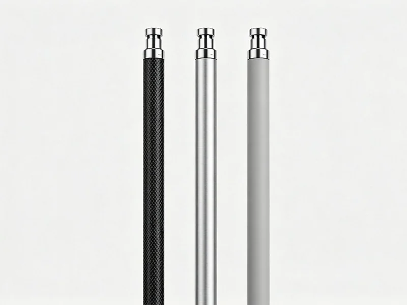
Three-Way Material Comparison
Aluminum has been the default antenna mast material for decades. Admittedly, it is inexpensive, widely available, and easy to work with. However, aluminum is a conductive metal — it blocks RF signals, detunes nearby antennas, and requires careful grounding to avoid becoming an unintentional radiator. In addition, aluminum corrodes in salt-air environments, developing surface oxidation that weakens joints and complicates maintenance.
Fiberglass (glass fiber reinforced polymer) is RF-transparent and corrosion-resistant, making it a common choice for low-frequency antenna radomes and small marine masts. Nevertheless, fiberglass has significantly lower stiffness than both aluminum and carbon fiber — a fiberglass mast of the same diameter deflects roughly 3× more under wind load. As a result, this limits fiberglass to short masts or installations with heavy guy-wire support. In a fiberglass vs aluminum antenna pole comparison, both materials lose to carbon fiber when stiffness and signal integrity are required simultaneously.
Carbon fiber combines RF transparency with high specific stiffness. Specifically, a carbon fiber tube weighs approximately one-third of an aluminum tube with equivalent bending resistance, and it does not corrode, shield signals, or require protective paint. Admittedly, the trade-off is higher upfront material cost — though for permanent outdoor installations, the zero-maintenance advantage often delivers lower total cost of ownership.
Property Comparison Table
| Property | Aluminum | Fiberglass | Carbon Fiber |
|---|---|---|---|
| RF Transparency | No — shields and reflects | Yes — fully transparent | Yes — fully transparent |
| Specific Stiffness | Good (~26 GPa / 2.7 g/cm³) | Low (~10 GPa / 2.0 g/cm³) | Excellent (~130 GPa / 1.6 g/cm³) |
| Corrosion Resistance | Poor — oxidizes in salt air | Good — resin protects fibers | Excellent — no rust or oxidation |
| Weight (25mm OD × 1m) | ~210 g | ~155 g | ~70 g |
| UV Degradation | Not affected | Resin can chalk without coating | UV coat recommended for outdoors |
| Thermal Expansion | High (23 ppm/°C) | Moderate (~8 ppm/°C) | Near zero along fiber axis |
| Upfront Cost | Low | Low–Medium | Higher |
| Maintenance | Regular inspection, repainting | Occasional coating renewal | Virtually none |
| Best Use Case | Budget indoor/temporary | Short radomes, low-load | Permanent outdoor, signal-critical |
RF Transparency: The Decisive Advantage
RF transparency means the support structure does not interact with the electromagnetic field radiated by the antenna. In practice, this translates to three measurable benefits:
No pattern distortion. First, a metal mast near a vertical antenna creates a parasitic element — it picks up and re-radiates signals, distorting the omnidirectional pattern into an unpredictable shape. Carbon fiber and fiberglass masts avoid this entirely, preserving the antenna designer’s intended radiation pattern.
No gain loss. Second, when a metal support absorbs and reflects RF energy, that energy does not reach the receiver. For weak-signal work — EME (moonbounce), VHF DX, satellite downlinks — even 0.5 dB of avoidable loss matters. Carbon fiber antenna tubes eliminate this loss path.
No detuning. Third, metal objects near an antenna shift its resonant frequency, requiring retuning or matching network adjustment. This is particularly problematic for multi-band antennas where a single metal mast can detune several bands simultaneously. Consequently, non-conductive supports keep the antenna on its designed frequency.
It is worth noting that carbon fiber is electrically conductive at the individual fiber level. However, the woven composite structure does not form a continuous conductive path. In RF field measurements, properly manufactured carbon fiber tubes show attenuation below 0.1 dB across HF through microwave bands — effectively transparent for all practical antenna applications. Therefore, an RF transparent antenna support made of carbon fiber introduces no measurable signal degradation.
How to Size Your Antenna Mast
Selecting the right dimensions for an antenna mast involves balancing stiffness, weight, and wind survival. Here are the key parameters:
Outer diameter is the primary driver of bending stiffness. For a thin-wall tube, bending stiffness scales with the cube of diameter — doubling the OD increases stiffness approximately 8×. As a practical guideline: 8–12mm OD for lightweight portable and drone antennas; 12–25mm OD for VHF/UHF verticals and WiFi masts up to 3m; 25–55mm OD for base-station antennas and multi-element arrays exceeding 3m.
Wall thickness, additionally, determines crush resistance and contributes to bending strength. For freestanding masts exposed to wind, 1mm minimum wall thickness is recommended. Heavier installations or high-wind regions benefit from 1.5–3mm walls. Conversely, thin-wall tubes (0.5mm) are suitable only for guyed masts or indoor applications where lateral loads are minimal.
Length must be evaluated against the self-weight deflection and wind-bending moment. For example, a 4m carbon fiber mast with 25mm OD and 1.5mm wall typically deflects less than 30mm under its own weight — compared to roughly 80mm for an equivalent fiberglass mast. For masts beyond 4m, use precision-fit joiner sleeves to connect multiple sections while maintaining bending continuity at the joint.
Wind Load: The Real-World Test
Wind load is the dominant structural demand on any antenna mast. Specifically, the force on a cylindrical mast scales with the square of wind speed and the projected area (OD × length). Therefore, a thinner mast inherently catches less wind — and carbon fiber’s high stiffness allows you to use smaller diameters without sacrificing rigidity.
Consider a typical scenario: a 3m mast supporting a 2kg VHF antenna in a 100 km/h wind zone. An aluminum mast needs at least 25mm OD to limit deflection to acceptable levels. In contrast, a carbon fiber mast achieves the same deflection with 20mm OD — reducing wind projected area by 20% and further decreasing the actual wind force on the structure. This virtuous cycle (stiffer → thinner → less wind load → less deflection) is unique to high-modulus materials like carbon fiber.
For guyed masts, wind load is partially transferred to the guy wires, allowing thinner tubes. On the other hand, for freestanding masts, choose roll-wrapped construction with ±45° fiber layers to resist bending from any wind direction. Meanwhile, pultruded tubes (0° unidirectional) are adequate for guyed installations where axial compression is the primary load.
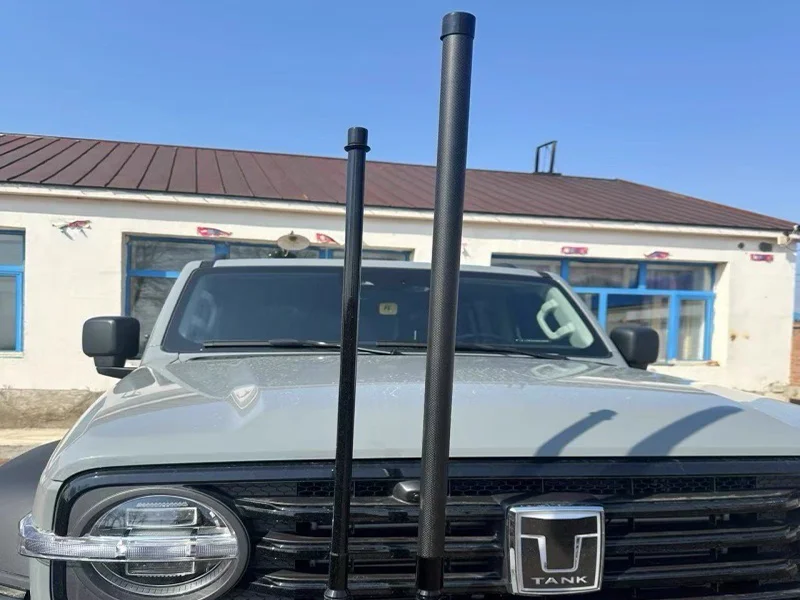
Quick Reference: Recommended Mast by Application
Construction Choice: Roll-Wrapped or Pultruded?
Both construction methods produce RF-transparent antenna tubes, but their mechanical behavior differs significantly under wind loading.
Roll-wrapped tubes use layered prepreg with customizable fiber orientations (0°/±45°/90°). Specifically, the ±45° layers resist torsion and lateral bending from any direction — exactly the loading pattern a freestanding antenna mast experiences in shifting winds. For this reason, roll-wrapped construction is the default recommendation for most antenna mast applications.
Pultruded tubes, on the other hand, align all fibers at 0° (unidirectional), maximizing axial compressive strength at lower cost. They perform well in guyed masts where the primary load is vertical compression and the guy wires handle lateral stability. However, without ±45° fiber layers, pultruded tubes are more susceptible to torsional and transverse bending, making them less ideal for freestanding installations.
In summary: freestanding mast → roll-wrapped; guyed mast on a budget → pultruded. Ultimately, both are available from YTCarbon with full customization of dimensions, surface finish, and UV coating.
Frequently Asked Questions
Signal & Material Questions
Sizing & Coating Questions
Need RF-Transparent Antenna Tubes?
Carbon fiber antenna tubes from 6mm ID. Roll-wrapped or pultruded. UV coating optional. Get a tailored factory-direct quote within 24 hours.